TCNC Usage
TCNC is designed as an Inkscape extension but can be also invoked as a standalone program from the command line to create G code from an SVG file. It does not require Inkscape to be installed to run.
Units
SVG has a concept known as user units which refers to the numeric values used to specify things like coordinates, distances, and dimensions. These values are scaled based on the viewBox attribute of the SVG root element. The SVG document size is specified using the SVG height and width attributes and they can be expressed using any valid SVG unit, such as pt, px, in, etc. This is referred to here as the document unit. Inkscape also has a display unit which is what is used for rulers.
G code units are either imperial or metric and specified as inches (G20) or millimeters (G21).
Together the document unit, user unit, viewBox, display unit, and G code unit can produce a beautiful (maddening) confusion. If these do not match it becomes difficult to infer the user’s intention with regards to scaling. In general, it is less confusing if the SVG units and drawing scale match the expected G code output.
TCNC will convert between the SVG document unit and the G code unit and further scale using the viewbox values. The viewbox aspect ratio must match the SVG width/height ratio.
To make things simple and to avoid conversion and scaling surprises it is recommended to specify the SVG drawing/document size using the G code unit (ie in or mm) and make the viewbox match the document size.
TCNC Inkscape Extension
To prepare a document to use with TCNC, set the display units in File->Document Properties… to either in or mm and use the same unit to specify the document size. Set scale to 1.0 to make the viewbox match the document. This is optional but strongly recommended since it helps to avoid unexpected unit conversion and scaling issues.
Select a path in Inkscape or select a layer if you want everything on that layer to be processed. If nothing is selected then all visible objects will be processed. From the Extensions menu select UTLCo -> TCNC.. and the TCNC extension dialog will appear.
TCNC only processes paths or basic shapes (circles, arcs, ellipses, rectangles, and spirals). Ellipses will be converted to Bezier curves before before conversion to circular arcs (biarcs). Text or other objects will be ignored.
The TCNC dialog
Tool Path Options
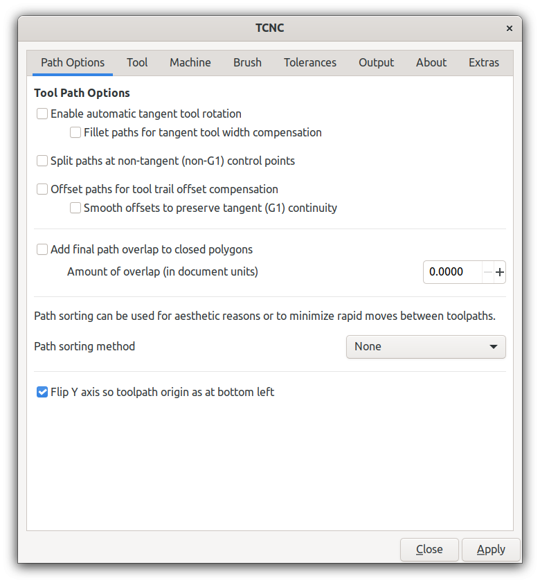
Enable tangent rotation
The A axis is automatically rotated during a feed so that the tool is always tangent to the direction of the XY movement. The A axis is assumed to rotate about the Z axis.
If not selected, the A axis will rotate to the initial A axis offset (if any) and stay at that angle.
Fillet paths for tool width compensation
Useful for wide brush-like tools. This will modify the path to add fillet arcs at corners to compensate for the tool width. It mitigates rotational artifacts caused by the wider tools.
This option is ignored if tangent rotation is disabled.
Close polygons with fillet
Adds a fillet between the end of the last segment of a path and the start of the first segment. Only applies if fillets are enabled.
Split paths at non-tangent control points
Split a path at non-tangent (no G1 continuity) control points (vertices). This is performed after any offsetting or filleting and creates separate tool paths for remaining non-tangent path sections.
Offset paths for tool trail offset compensation
Offsets the path segments to compensate for tool trail offset. Tools with a trail offset will follow the original path much more closely at the cost of tool path complexity and possible acceleration/deceleration artifacts.
Add final smoothing fillets
This will add small fillets to non-tangential vertices of the path after offsetting. Probably not useful if the machine already provides trajectory blending.
Add final path overlap to closed polygons
Adds a segment to the end of a path that defines a closed polygon to overlap the start segment.
Path sorting method
Sort paths for aesthetic reasons or to minimize rapid moves between tool paths.
- Flip paths
Use original path order but flip (reverse) paths to shorten rapid moves.
- Bottom to top, left to right
Sorts the paths from bottom to top and secondarily left to right.
Flip Y axis
Flip Y axis so that the tool path origin is at the lower left. This matches more closely the expected machine coordinates.
By default the SVG (and Inkscape) coordinate system sets the origin at the top left corner of the document. This makes it awkward to visualize the tool travel since most CNC machines set the origin at the lower left of the XY plane.
Tool Options
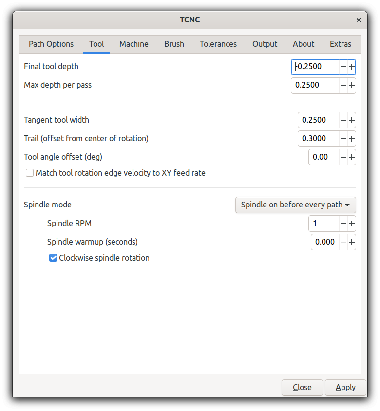
Final depth
The final tool depth of the last pass. Depth per pass and final depth can be the same if just one pass is required.
Depth per pass
Maximum Z depth per pass if multiple passes are needed per path. This value can be negative or positive - the absolute value will used used as distance of travel towards the final depth. Ignored if the value is zero.
Tool width
Width in document units of the tangential tool such as a brush, scraper, or squeegee. This will determine fillet radius if tool path compensation fillets are enabled.
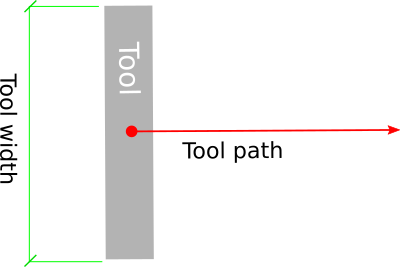
Fig 2. Tool width
Trail offset
Tool trail offset is the distance from the center of rotation to the point of contact with the surface. Flexible tools such as brushes and scrapers will deflect when brought to the work surface. This creates a trailing point of contact and will cause unwanted behavior when making relatively tight turns. TCNC will try to recalculate the path to compensate for this so that the center of contact follows the original path more closely.
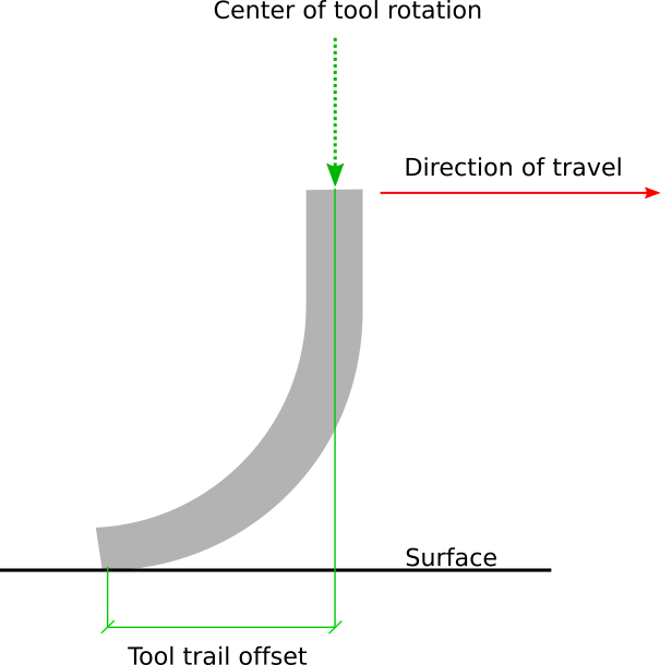
Fig 3. Tool trail offset
Tool angle offset
Offset in degrees of the A axis.
Match tool rotation edge velocity
Adjust angular feed velocity so that angular velocity of the the outer rotating tool edge matches the XY feed velocity. This is only relevant for non-zero width tangent tools.
Spindle mode
No spindle
Spindle on at start
Spindle on before every path
Spindle RPM
Spindle speed in revolutions per minute.
Spindle warmup
Time in seconds to wait for the spindle to get up to speed and warm up.
Clockwise spindle rotation
Direction of spindle rotation. Default is clockwise.
Machine Options
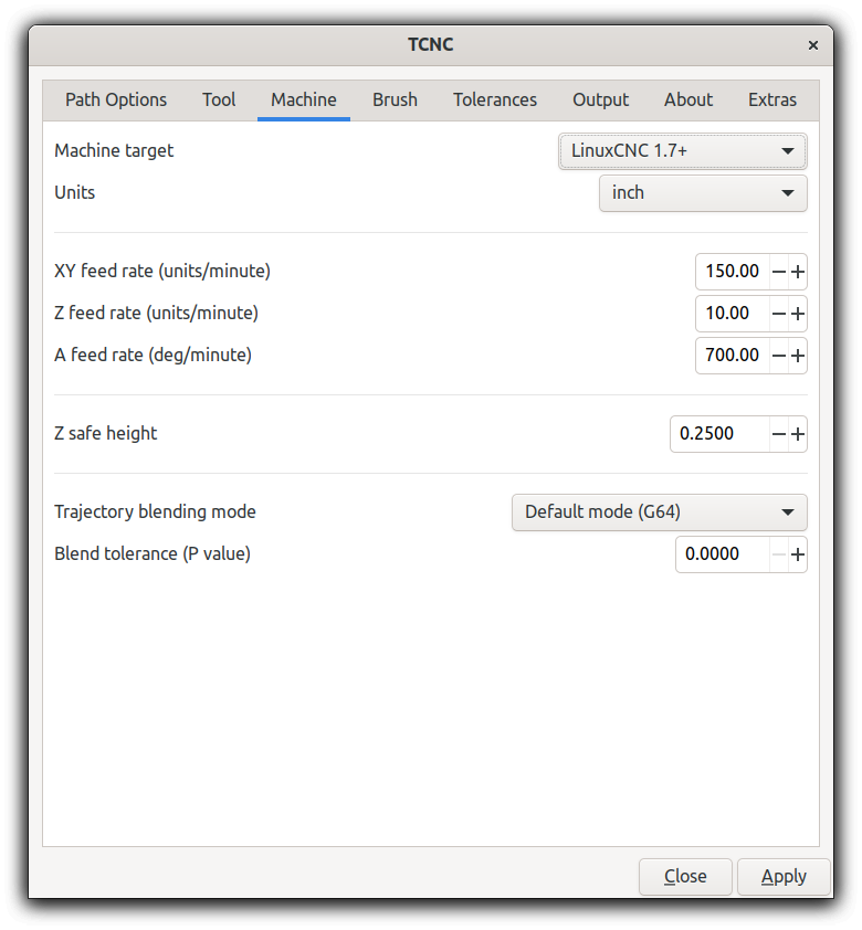
Machine target
G code interpreter. This is LinuxCNC v1.7+ by default.
Other interpreters may or may not be supported.
Units
G code (machine) units. These can be inches or millimeters.
- Infer from document
Inches or mm inferred from document units. For example if the document is in imperial units then inches will be used, otherwise mm.
inch
mm
XY feed rate
The feed rate of the X and Y axes. In machine units per minute.
Z feed rate
The Z axis (vertical) feed rate. In machine units per minute.
A feed rate
The A (rotational) axis feed rate. In degrees per minute.
Z safe height
The safe height, in machine units, of the Z axis for rapid moves.
Trajectory blending mode
Tool path blending mode used by the machine controller.
- Default (G64)
The default blending mode which is usually G64 - blending with a default tolerance.
- Blend with tolerance (G64 P`t`)
G64 blending with a specified tolerance.
- Exact path (G61)
Follow the exact path with no blending. Accurate but can be slow. The tool may come to a complete stop at path vertices.
Blend tolerance
The blend tolerance (P) value when using the G64 P`t` blend mode.
Brush Options
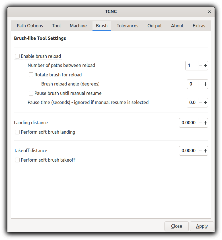
Enable brush reload
Brushes often require more paint and this enables a brush reload sequence for manual brush reloading. Automated brush reloading is not currently supported since it would be extremely machine dependent.
Number of paths between reload
Number of paths to output before a reload sequence is performed.
Rotate brush for reload
Rotate the brush to the specified reload angle before each path.
Pause brush until manual resume
Issue a pause command which will wait until the user starts/unpauses the machine. Usually this is done via Axis or some other UI.
Brush pause time
Amount of time in seconds that the tool feed will pause to allow manual reloading of the brush. This is ignored if manual resume is enabled.
Landing distance
Prepend a line segment of this length to the tool path that is tangent to the first tool path segment.
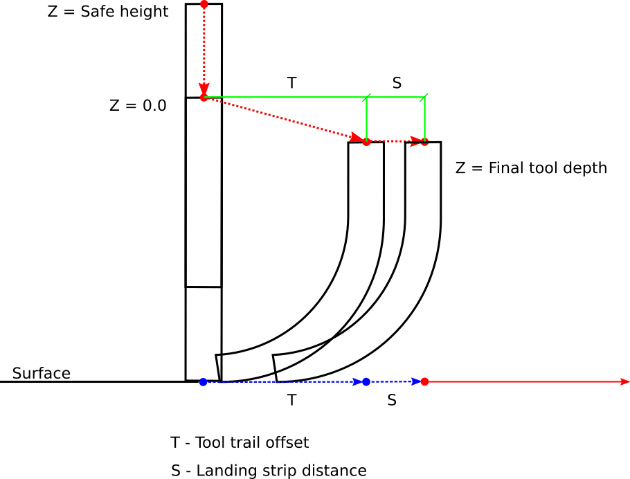
Fig 4. Soft landing Z axis trajectory
Perform soft brush landing
A flexible tool such as a brush will develop its trail distance only after touching and pressing into the work surface. This will use the Z depth and landing distance to create a ramp trajectory along the Z and XY axes.
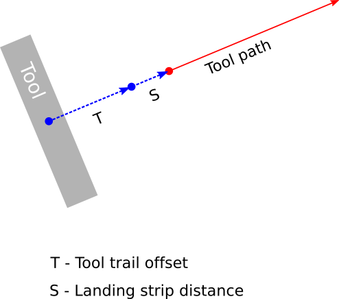
Fig 5. Soft landing XY axis trajectory
Takeoff distance
Append a line segment of this length to the tool path that is tangent to the last segment of the tool path.
Perform soft brush takeoff
Create a ramp trajectory along the takeoff segment, rising along the Z axis to the Z safe height.
Tolerance Options
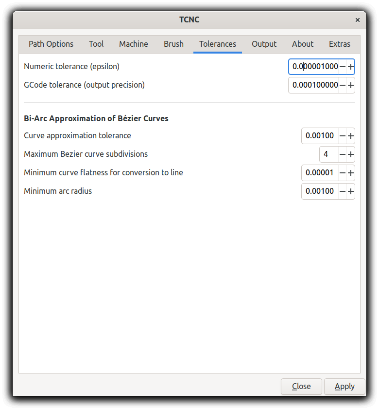
Numeric tolerance
This determines the numeric tolerance (epsilon) of floating point comparisons.
G code tolerance
The G code output precision. Determines the maximum number of digits after the decimal point.
Curve approximation tolerance
The maximum distance, in document units, between the approximation and the original curve. Smaller values can result in more accurate approximations but at the expense of slower performance.
Maximum Bezier curve subdivisions
Inkscape paths consist of Bezier curves and to accurately approximate them with circular arcs they may need to be broken down into smaller curves. Larger values can result in more accurate approximations but at the expense of slower performance.
Curve to line flatness
Curves that are flatter than this will be approximated by a straight line. Flatness is the maximum distance from a line between the curve end points and the curve. In document units.
Minimum arc radius
Arcs with a radius smaller than this will be replaced by a straight line. In document units. This can avoid unexpected rotations of the tangential tool when encountering tiny spurious curves that might be in the input path.
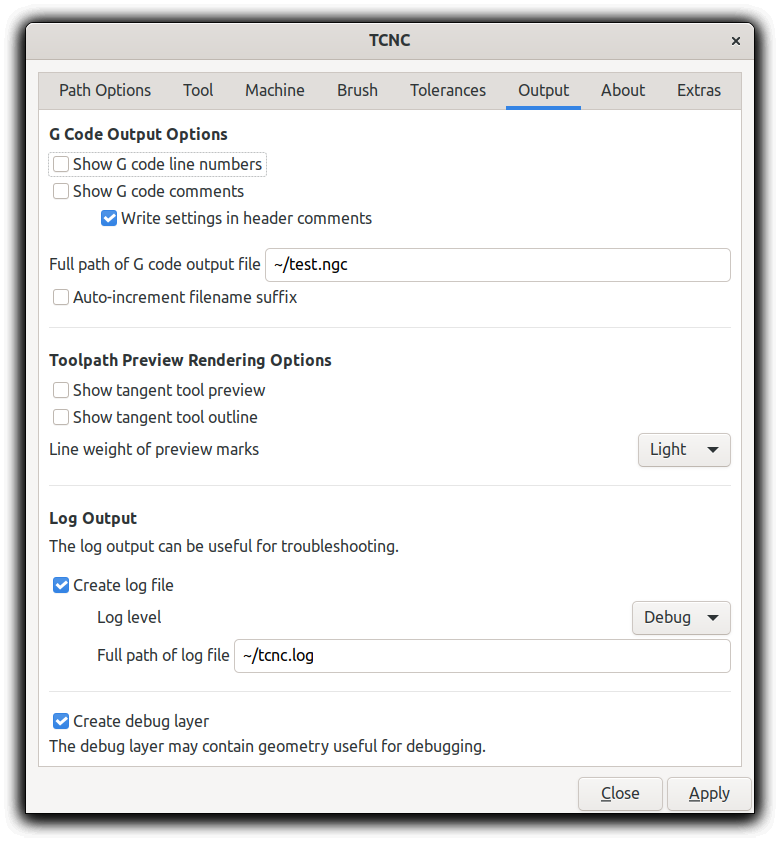
Output Options